شرکت تدبیر انرژی امید

شرکت تدبیر انرژی امید
دنبال کنندگان ۴ نفر
این وبلاگ را دنبال کنید
طبقه بندی موضوعی

۷۸ مطلب در آذر ۱۳۹۴ ثبت شده است

سه شنبه, ۱۰ آذر ۱۳۹۴، ۱۰:۵۴ ب.ظ

Reliability Optimization through Component Condition and Root Cause Analysis

Forsthoffer's Rotating Equipment Handbooks Vol 5: Reliability Optimization through Component Condition and Root Cause Analysis


همانگونه که در مطلب هزینه چرخه عمر پمپ و مبحث آشنایی با استاندارد API610 نیز ذکر شده بود  یکی از با اهمیت ترین مباحث در خصوص  تجهیزات دوار، اطمینان پذیری آنها در فرآیندها می باشد.

باید توجه داشت که بحث قابلیت اطمینان تجهیزات از ابتدای مراحل طراحی تاسیسات و خرید تجهیزات شروع می شود که این موضوع می بایست از ابتدا در تهیه مشخصات خرید دستگاه لحاظ گردد.

با توجه به اهمیت موضوع فوق در صنایع به خصوص صنایع نفت و گاز پتروشیمی از امروز هر هفته یک بخش از کتاب فوق که از انتشارات Elsevier Science & Technology Books  می باشد برای علاقه مندان به اشتراک گذاشته می شود.

 تاریخ به اشتراک گذاری بخش بعد 17-9-94 می باشد.

1 - Reliability overview, Pages 1-11

Download link:

Section 1- Reliability overview
حجم: 717 کیلوبایت


۰ نظر موافقین ۰ مخالفین ۰ ۱۰ آذر ۹۴ ، ۲۲:۵۴
سه شنبه, ۱۰ آذر ۱۳۹۴، ۱۰:۱۷ ب.ظ

استانداردهای API

برای دریافت استانداردهای زیر به بخش استانداردها مراجعه نمایید


American Petroleum Institute (API)

  • API 610 11th Edition (Centrifugal Pumps for Petroleum, Petrochemical and Natural Gas Industries)
    • عنوان: API 610 11th edition
      حجم: 9.12 مگابایت
  • API 610 10th Edition (Centrifugal Pumps for Petroleum, Petrochemical and Natural Gas Industries)
۳ نظر موافقین ۰ مخالفین ۰ ۱۰ آذر ۹۴ ، ۲۲:۱۷
سه شنبه, ۱۰ آذر ۱۳۹۴، ۰۶:۵۴ ق.ظ

ملات ریزی (Grouting)

آموزش نصب پمپ های سانتریفوژ - بخش 4


ملات ریزی (Grouting)


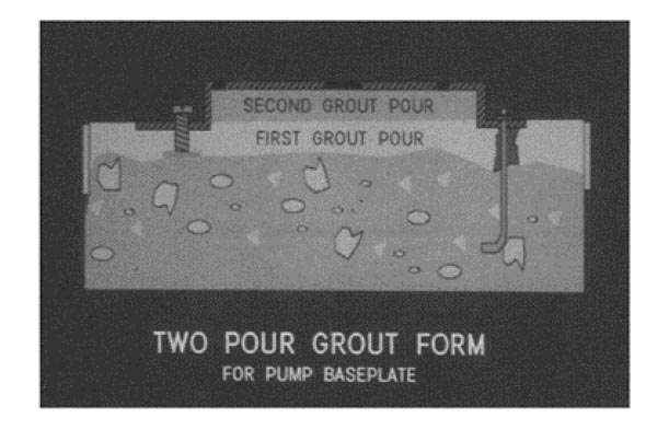
معمولا زیر شاسی قبل از نصب اتصالات لوله­ کشی و کنترل نهایی هم محوری نیمه­ های کوپلینگ، ملات ریزی می­شود. ملات­ریزی به منظور جلوگیری از حرکت­ های جانبی شاسی، افزایش جرم به هدف کاهش ارتعاشات و پر کردن بی­نظمی­ های موجود در پی انجام می­گیرد. در هنگام نصب دائمی تجهیزات پمپاژ عموما توصیه می­شود تا از سازه­ های ساخته شده از بتن مسلح به عنوان پی استفاده شود. برای نصب پمپ­ها در ارتفاع و یا حالت های خاص ممکن است از سازه­ های فولادی برای نصب پمپ­ها استفاده شود. در این حالت باید دقت لازم صورت گیرد تا از مقاومت و سختی مناسب سازه، اطمینان حاصل شود. برای طراحی ابعاد پی باید اندازه و چیدمان پمپ و موتور، چیدمان لوله کشی و بارهای وارده از سیستم لوله ­کشی، محل پیچ­های پایه و حداقل فضای لازم برای سرویس تجهیزات در نظر گرفته شود.

پی پمپ­های عمودی Can Type باید به گونه ­ای طراحی شود تا پمپ مستقیما به صفحة نصب (Mounting Plate) متصل بشود و بتوان پمپ را بدون آنکه به ملات ریزی صدمه وارد شود جابجا کرد.

مواد تشکیل دهنده پی باید مقاومت کافی نسبت به مواد شیمیایی و روغن­ها داشته باشند. در صورتی که محیط مهاجم باشد، باید روکش و یا پوشش محافظ مناسب برای پی و فولادهای تقویت کننده در نظر گرفته شود. برای ملات ریزی معمولا از دو نوع ملات استفاده می­شود: ملات­های متشکل از مواد اپوکسی و ملات­های با پایة سیمان. ملات­های اپوکسی دارای قیمت بالاتری هستند ولی در عوض مقاومت آنها بالاتر بوده و سطح نهایی بدست آمده صاف بوده و دارای خلل و فرج نمی­باشد. به علت مزایای این ملات هاعموما از آنها برای ملات ریزی اغلب پمپ­ها استفاده شود.

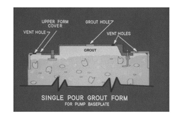
جنس ملات با توجه به جنس پی معین می­شود. بعد از اینکه پی آماده شد شاسی بر روی آن قرار داده شده و هم محورسازی اولیه بین پمپ و موتور انجام می­شود تا از هم محور شدن نهایی پمپ و موتور پس از انجام عملیات ملات ریزی اطمینان حاصل شود. بعد از انجام هم محورسازی اولیه ملات از طریق سوراخهایی که برای ملات­ریزی شاسی در نظر گرفته شده است، ریخته می­شود. برای نگهداری ملات در محل مورد نظر در اطراف شاسی موانعی ایجاد می­شود. عملیات ملات­ریزی تا زمانی که تمامی فضای زیرشاسی پر شود ادامه می­یابد.

سوراخهایی که برای ملات­ریزی بر روی شاسی در نظر گرفته شده است این امکان را فراهم می ­آورد تا هوای زیر شاسی هنگام ملات ریزی تخلیه شود. برای هم زدن ملات و آزاد کردن حبابهای هوای محبوس در آن می‌توان از سیم سختی استفاده کرد. معمولا بهتر است، ملات ریزی از یک سمت انجام شود تا با پیش روی ملات به زیرشاسی هوای زیر آن بتواند از سمت دیگر تخلیه شود. صفحات و گوه­های فلزی که برای تراز کردن به کار رفته­ اند، بعد از پایان ملات ریزی درجای خود باید باقی بمانند.

پس از سفت شدن ملات حفره­ های باقی مانده پر شده و قالب­ها برداشته می­شوند. در صورت نیاز سطوح پی پرداخت می­شوند. پیچهای پایه و نگهدارنده به اندازه لازم محکم شده و هم محوری نیمه­ های کوپلینگ کنترل می­شود.

بعد از سخت شدن کامل ملات هم محوری پمپ و موتور باید کنترل شود و پس از این مرحله عمل کنترل هم محوری پمپ و موتور باید در فواصل زمانی مناسب انجام گیرد.


۰ نظر موافقین ۰ مخالفین ۰ ۱۰ آذر ۹۴ ، ۰۶:۵۴
دوشنبه, ۹ آذر ۱۳۹۴، ۱۰:۳۶ ب.ظ

Panel Discussion on Inducer Design Criteri

Panel Discussion on Inducer Design Criteria


معیار های طراحی ایندیوسر


This article reports a panel discussion titled Inducer Design Criteria presented at the 9th International Symposium on Transport Phenomena and Dynamics of Rotating Machinery (ISROMAC-9). The presentations of the panelists and the subsequent discussions are summarized. It is shown that cavitation instabilities are major problems in modern turbopumps and that design criteria to eliminate them are needed. Available design methods for inducers and marine propellers are reviewed, and new criteria to enhance stability are proposed. The current status of CFD is reviewed and an example of successful application is shown. Discussions of several specific topics are reported and future research needs are noted.


Download link:

Panel Discussion on Inducer Design Criteria
Size: 909KB


۰ نظر موافقین ۰ مخالفین ۰ ۰۹ آذر ۹۴ ، ۲۲:۳۶
يكشنبه, ۸ آذر ۱۳۹۴، ۰۷:۱۲ ب.ظ

Optimization of Vane Diffuser in a Mixed-Flow Pump for High Efficiency Design

Optimization of Vane Diffuser in a Mixed-Flow Pump 

for High Efficiency Design


Abstract

This paper presents an optimization procedure for high-efficiency design of a mixed-flow pump. Optimization techniques based on a weighted-average surrogate model are used to optimize a vane diffuser of a mixed-flow pump.

Validation of the numerical results is performed through experimental data for head, power and efficiency. Three-level full factorial design is used to generate nine design points within the design space. Three-dimensional Reynoldsaveraged Navier-Stokes equations with the shear stress transport turbulence model are discretized by using finite volume approximation and solved on hexahedral grids to evaluate the efficiency as the objective function. In order to reduce pressure loss in the vane diffuser, two variables defining the straight vane length ratio and the diffusion area ratio are selected as design variables in the present optimization. As the results of the design optimization, the efficiency at the design flow coefficient is improved by 7.05% and the off-design efficiencies are also improved in comparison with the reference design.

Keywords: Mixed-flow pump, Impeller, Vane diffuser, Efficiency, Optimization, Weighted-average surrogate model.


Download Link:

Optimization of Vane Diffuser in a Mixed-Flow Pump for High Efficiency Design

Size: 606 KB

۰ نظر موافقین ۰ مخالفین ۰ ۰۸ آذر ۹۴ ، ۱۹:۱۲
يكشنبه, ۸ آذر ۱۳۹۴، ۰۶:۵۷ ب.ظ

Assessment Of A Mixing Plane Method For CFD Analysis

Multistage Centrifugal-Pumps: Assessment Of A Mixing Plane 

Method For CFD Analysis


Abstract

An accurate CFD investigation allows a thorough knowledge of the fluid dynamic field inside a multistage centrifugal pump but only a correct interpretation of its results grants a well-founded prediction of the machine performance curves. The paper introduces the assessment of an improved methodology to predict head-flow and efficiency characteristics of industrial pumps in real operating conditions. The described approach is based on standard CFD analysis and experimental tests.


The numerical procedure is built-up of three different steps:

· CFD investigation of the single impeller and diffuser domains;

· impeller-diffuser interaction analysis;

· evaluation of the whole multistage pump performance curves by pressure field


interpretation and taking into account real machine secondary phenomena. The stage computational model is made up of two 3D fluid domains with overlapping: one of them is aimed to simulate the diffuser and is related to a stationary reference frame while the other one models the impeller and is referred to a rotating system.

Moreover the impeller–diffuser interaction is studied by the employment of a mixing plane technique. Numerical results are then compared to the real pump performance test at the actual working conditions in order to validate the proposed methodology.

The paper will discuss all approach details and the main CFD features involved.


Download Link:

Multistage Centrifugal-Pumps: Assessment Of A Mixing Plane Method For CFD Analysis
Size:567 KB


۰ نظر موافقین ۰ مخالفین ۰ ۰۸ آذر ۹۴ ، ۱۸:۵۷
يكشنبه, ۸ آذر ۱۳۹۴، ۰۶:۴۳ ب.ظ

Design and CFD Analysis of Centrifugal Pump

Design and CFD Analysis of Centrifugal Pump


Abstract— the purpose of this paper is to identify /observe and determine the pattern of velocity profile and pressure distribution by using CFD simulation program after the 3D design and modeling of the pump is made using Vista CPD. Basically, this paper revolves around the idea of investigating the effect and distribution of velocity profile and pressure within a pump having the following specification, Head = 20 m, Flow rate = 280 m3/hr, and RPM = 1450. 3D Navier–Stokes equations were solved using ANSYS CFX.

The standard k -e turbulence model was chosen for turbulence model. From the simulation results it was observed that the pressure increases gradually from impeller inlet to outlet. The static pressure on pressure side is evidently larger than that on suction side at the same impeller radius. In addition to this, it was observed that, the velocity increases from impeller inlet until it enters the volute casing. It then drops to a minimum value at outlet region.


KeywordsCentrifugal pump design, CFD Analysis, Simulation, ANSYS CFX, Vista CPD, pressure distribution, CFD-Tool.


Download Link:

Design and CFD Analysis of Centrifugal Pump
Size:786 KB


۰ نظر موافقین ۰ مخالفین ۰ ۰۸ آذر ۹۴ ، ۱۸:۴۳
يكشنبه, ۸ آذر ۱۳۹۴، ۰۶:۳۳ ب.ظ

CFD Simulation of Centrifugal Pump Impeller Using ANSYS-CFX

CFD Simulation of Centrifugal Pump Impeller Using 


ANSYS-CFX


ABSTRACT: Centrifugal pumps are a most commonly used in different fields like industries, agriculture and domestic applications. Computational Fluid Dynamics is most commonly used tool for simulation and analysis. 3-D numerical CFD tool is used for simulation of the flow field characteristics inside the turbo machinery. CFD simulation makes it possible to visualize the flow condition inside centrifugal pump. The present paper describes the head, power, efficiency and to evaluate the pump performance using the ANSYS CFX-14, a computational fluid dynamics simulation tool. These simulations of centrifugal pumps are strongly related to cavitation flow phenomena, which may occur in either the rotating runner-impeller or the stationary parts of the centrifugal pumps. The numerical simulation can be used to detect the cavitation in centrifugal pump and to get safe range of operating at different flow rate and rotating speed.

KEYWORDS: Centrifugal pump impeller, CFD, Head, Power, Efficiency, Cavitation.


Download Link: 

CFD Simulation of Centrifugal Pump Impeller
Size: 1.2 MB


۱ نظر موافقین ۰ مخالفین ۰ ۰۸ آذر ۹۴ ، ۱۸:۳۳
شنبه, ۷ آذر ۱۳۹۴، ۱۰:۴۳ ب.ظ

Vibration modal analysis

۰ نظر موافقین ۰ مخالفین ۰ ۰۷ آذر ۹۴ ، ۲۲:۴۳
شنبه, ۷ آذر ۱۳۹۴، ۰۸:۲۷ ب.ظ

مجموعه اجزا دوار (Rotor)

دوره کامل آموزش پمپ های API610  (پمپ های فرآیندی)- بخش دوازده

مجموعه اجزا دوار (Rotor):

تعریف اجزا دوار: به مجموعه مونتاژ شده قطعات دوار پمپ گفته می شود.

          ·        پروانه ها می بایست بسته (Enclosed)، نیمه باز (Semi-open) یا باز(Open) باشند.

پروانه های بسته به موقعیت محوری حساسیت کمتری دارند لذا برای حالت هایی به دلایلی مانند تغییرات دمایی و یا نیرو های محوری امکان جابجایی وجود دارد گزینه مناسبی هستند. پمپ های نیمه باز دارای بازده بالاتری  هستند. در پمپ های عمودی موقعیت پروانه های نیمه باز را می توان با استفاده از Adjusting coupling تنظیم کرد. لذا راندمان پمپ را می توان بدون باز کردن آن در صورت لزوم بازیابی کرد. پروانه های باز عموما پروانه های جریان محوری بوده که می توانند دبی بالا با هد کم تولید کنند.

          ·        پروانه باید به صورت یکپارچه ساخته شود

          ·        پروانه پمپ باید بوسیله خار به محور متصل شود, استفاده از پین برای اتصال پروانه به محور قابل قبول نمی‌باشد. در پمپهای Overhung برای محکم کردن پروانه به محور باید از پیچ‌های کلاهی (Cap Screw) و مهره‌های کلاهی (Cap Nut) استفاده شود. رزوه پیچ و یا مهره نگهدارنده پروانه می بایست باید به گونه‌ای باشد، که نیروهای وارد به آنها تمایل به محکمتر کردن آنها داشته باشند و در ضمن این اجزاء را باید با روش موثری قفل کرد تا از حرکت کردن آنها جلوگیری شود.

          ·        تمام جا خارها مطابق استاندارد ISO 3117 می بایست Fillet بخورند.

          ·        تلرانس عبوری Shaft sleeve بر روی شف می بایست بر اساس استاندارد ISO286 معادل F7/h6 باشد.

          ·        تمام طول محور پمپ باید ماشینکاری و پرداخت شده و Total Indicated Runout آن نباید بیشتر از mm 25 باشد.

          ·        برای اینکه عملکرد آب بندی‌ها مطلوب باشد حداکثر مقدار خیز در سخت‌ترین شرایط دینامیکی محدوده عملکرد مجاز پمپ در محل رینگ آب بندی اولیه
(Primury Seal Face) نباید از mm 50 بیشتر باشد.

۰ نظر موافقین ۰ مخالفین ۰ ۰۷ آذر ۹۴ ، ۲۰:۲۷